|
NaNH2 - Part 2
|
In this second part of our laboratory experience, we will introduce some new specific keywords that are commonly present in a CRYSTAL input for a periodic system and we are going to simulate and study typical properties (band structure, density of states, electron charge density) of solid systems.
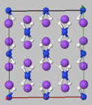
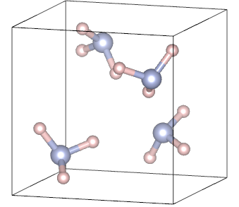
For this purpose, we will start analyzing the case of solid ammonia.

Periodic systems and their properties - Solid NH3 case
i) Input for a crystalline system – NH3
Below a standard CRYSTAL input for crystalline NH3 is presented:
Ammonia crystal
CRYSTAL
0 0 0
198
4.9127
2
1 0.0973 0.3665 0.2741
7 0.2023 0.2023 0.2023
END
7 4
0 0 6 2. 1.
0.417351E+04 0.183477D-02
0.627458E+03 0.139946D-01
0.142902E+03 0.685866D-01
0.402343E+02 0.232241E+00
0.128202E+02 0.469070E+00
0.439044E+01 0.360455E+00
0 1 3 5. 1.
0.116264E+02 -.114961E+00 0.675797D-01
0.271628E+01 -.169117E+00 0.323907E+00
0.772218E+00 0.114585E+01 0.740895E+00
0 1 1 0. 1.
0.212031E+00 0.100000E+01 0.100000E+01
0 3 1 0. 1.
0.800000E+00 0.100000E+01
1 3
0 0 3 1.0 1.0
.1873113696D+02 .3349460434D-01
.2825394365D+01 .2347269535D+00
.6401216923D+00 .8137573262D+00
0 0 1 0.0 1.0
.1612777588D+00 .1000000000D+01
0 2 1 0.0 1.0
.1100000000D+01 .1000000000D+01
99 0
END
DFT
PBE0-D3
END
SHRINK
6 6
MULPOPAN
END
Two substantial changes are introduced in this current input respect to that constructed for ammonia molecule. The first one is in the geometry section, where instead of MOLECULE keyword, CRYSTAL is specified, because we intend to perform calculations on a 3D system. This keyword is followed by three numbers, that in this case are all 0, that are related to convention of space group identification, type of cell and setting for the origin of the crystal reference frame. We do not provide further details about the meaning of these numbers, but you can find their explanation in the CRYSTAL manual. In the subsequent line, the space group label of the crystal is specified (space group 198, P213), followed by the minimal set of crystallographic cell parameters that in our case is just the a lattice parameter, since the system is cubic. Then, the number of non-equivalent atoms in the asymmetric unit is specified with the indication of the atomic number and fractional coordinates of each of them. The second difference is found in the Hamiltonian section, where the SHRINK keyword appear, for the specification of the shrinking factor, mandatory input information for 3D systems. The shrinking factor gives indication about how to generate a commensurate grid of k points in reciprocal space, according to Pack-Monkhorst method.
Exercise:
Basing on the provided sample input, perform the calculation with HF method and PBE0-D3, PBE and SVWN functionals. Study the effect of the functional and/or method on total energy, N and H Mulliken charges, band gap and overlap population (OVPOP) of the N-H bond.
ii) Properties of solid systems
From a CRYSTAL calculation, different properties can be computed by running a PROPERTIES calculation (filename.d3). At the end of the SCF process, the program writes information on the crystalline system and its wave function as unformatted sequential data in Fortran unit 9, that cannot be modified. From the information included in such file, it is possible to calculate different one-electron properties as band structure, density of states and electron charge density. In each folder where you will run PROPERTIES calculation, the relative fort.9 file must be present for the computation.
- Band structure
- Select ‘Make a plot’
- Select ‘Band structure plot’
- Import file.25 obtained as one of the outputs of the calculation
- Rename k points, change the y axis unit,…
- Density of states
- NEWK
8 8
1 0
DOSS
2 200 5 36 1 14 0
-1 1
-1 13
END - NEWK
8 8
1 0
DOSS
4 200 5 36 1 12 0
5 1 2 61 62 66
6 3 4 63 64 67 68
3 5 65 69
5 70 71 72 73 74
END - ‘Make a plot’
- ‘Density of states plot’
- Import file.25 obtained as one of the outputs of the calculation
- Change the x axis unit, line labels…
- ‘Make a plot’
- ‘Unified plot of band structure and density of states’
- Import file.BAND and file.DOSS obtained as one of the outputs of band structure and DOSS calculations, respectively
- Modify plot settings
- Electron charge density
- ‘Make a plot’
- ‘Electron charge density map’
- Import file.25 obtained as one of the outputs of the calculation
- ‘Make a plot’
- ‘Difference map from a single file’
- Import file.25 obtained as one of the outputs of the calculation
The band structure along a given path in the Brillouin zone is computed. Below we report the sample PROPERTIES input for crystalline NH3.
BAND
Path G X M R G
4 8 120 5 36 1 0
0 0 0 0 4 0
0 4 0 4 4 0
4 4 0 4 4 4
4 4 4 0 0 0
END
The input looks quite different respect to that of a typical CRYSTAL calculation. In the first line the keyword BAND specifies the one-electron property you want to compute. The second line is the title. Also in this case, it can be whatever you want but must be present. Then 7 numbers are specified: the number of segments in the reciprocal space to explore; shrinking factor; total number of k-points along the path; first band to be saved; last band to be saved; plotting option; printing option.
A number of rows follows, equal to the indicated number of segments, that specify the path in the Brillouin zone. To have information about k-points and Brillouin zone of a given space group, have a look at BILBAO Crystallographic server.
Note that the coordinates of the extreme of the segments are all multiplied by the shrinking factor.
To visualize the calculated band structure, you can use Crysplot:
Exercise:
Calculate the band structure of NH3 with all adopted functionals for the calculation of total energy of NH3 . The input will always be the same but be careful to use the correct fort.9 file where wavefunction and Hamiltonian information are stored.
Which difference do you notice?
Density of state of the system is computed. Below we report two similar but different sample PROPERTIES inputs for crystalline NH3.
In both cases, NEWK keyword is inserted to specify the shrinking factor, that could be different from that of previous CRYSTAL calculation. It is needed for the calculation of eigenvectors. 1 and 0 are referred to evaluation of the Fermi level with the new k-points net and printing options, respectively. Keyword DOSS activates the computation of density of states of the investigated system.
Now two kinds of computation can be chosen: i) calculation of density of states projected onto the whole set of atomic orbitals of an indicated atom; ii) calculation of density of states projected onto a specific set of atomic orbitals. The first reported input is referred to the first mentioned possibility. 7 numbers are specified: number of projections; number of points along the energy axis in which the DOSS is calculated; first band; last band; plot option; degree of the polynomial used for the DOSS expansion; printing option. A number of rows follows, equal to the indicated number of projections, to indicate the projection of all atomic orbitals (-1) of an atom, which is indicated with the correspondent label in the CRYSTAL output.
The second input is referred, instead, to the second possibility. 7 numbers are again specified, which have exactly the same meaning explained above. In this case, however, the following lines are constructed in a different way, since now we want to specify sets of orbitals onto which project the density. The first number is related to the number of orbitals you are going to indicate in the same line. The following numbers are, instead, the label of orbitals as found in CRYSTAL output onto which project the density. Usually they are group by type (e.g. first line s orbitals, second line p orbitals and so forth).
To visualize the calculated DOSS, you can use Crysplot:
Moreover, it is also possible to visualize band structure plot and DOSS plot together:
Exercise:
Calculate the density of states of NH3 with all adopted functionals for the calculation of total energy of NH3. The input will always be the same but be careful to use the correct fort.9 file where wavefunction and Hamiltonian information are stored.
Which difference do you notice?
Electron charge density can give you information about concentration of charge along covalent bonds, the nearly uniform distribution of the conduction electrons in metals, the core expansion or contraction. Below a sample PROPERTIES input for calculation is reported:
ECHG
0
100
COORDINA
-4. -4. 0.0
4. -4. 0.0
4. 4. 0.0
MARGINS
2.0 2.0 2.0 2.0
END
PATO
0 0
ECHG
0
100
COORDINA
-4. -4. 0.0
4. -4. 0.0
4. 4. 0.0
MARGINS
2.0 2.0 2.0 2.0
END
END
ECHG is the keyword to activate electron charge density computation. The second line refers to the order of derivatives, followed by the number of points along the A-B segment. COORDINA keyword is followed by three lines where the cartesian coordinates of A, B and C points are specified to define the window in a plane. MARGINS keyword define the addition of margins to the window, whose width is indicated in the subsequent line. PATO keyword allows to compute with a single input also the difference map, which is very useful to gain further insights into the system. The difference map is obtained by the difference between the crystal electron density and a "reference" electron density, calculated as a superposition of atom densities.
To visualize electron charge density map, you can use Crysplot:
You can also visualize the difference map:
Exercise:
Calculate the electron charge density of NH3 with all adopted functionals for the calculation of total energy of NH3. The input will always be the same but be careful to use the correct fort.9 file where wavefunction and Hamiltonian information are stored.
Which difference do you notice?